The data acquisition (DAQ) software is used to interactively control the APV setup hardware and read out the analog data, which are written to disk. Moreover, it provides an online analysis for monitoring purposes. The offline analysis software, using a refined code with additional features, reads the data from disk and performs an extended evaluation.
Both versions of the APV software run in the LabWindows/CVI environment by National Instruments on a PC under Windows NT. While providing the same graphical user interface (GUI) features as the wide-spread LabView package, the CVI software is entirely written in the C programming language.
The data are not acquired continuously for lack of disk space, but in single runs with a defined set of parameters and conditions. Such a run consists of an initialization phase with pedestal and noise evaluation followed by the main part of data acquisition.
Depending on the intention of the operator, various run types are possible in the HEPHY APV readout system:
Each run follows a certain sequence:
Fig.
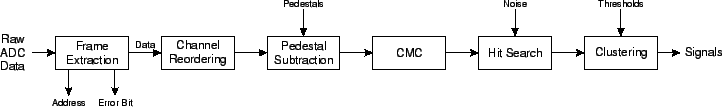
![[*]](crossref.gif) illustrates the calculations performed on a single event.
The input of the event processing algorithm are the raw ADC data. The APV output frame(s) must
be extracted from this data stream, returning the pipeline address, the error bit
and the channel data. Due to the APV output multiplexer, the channel output order does not
correspond to the physical order (see section , p. ) and thus must be reordered.
illustrates the calculations performed on a single event.
The input of the event processing algorithm are the raw ADC data. The APV output frame(s) must
be extracted from this data stream, returning the pipeline address, the error bit
and the channel data. Due to the APV output multiplexer, the channel output order does not
correspond to the physical order (see section , p. ) and thus must be reordered.
Then, the pedestal (zero input) values are subtracted for each channel, which is also known as zero-suppression. Low-frequency noise such as an AC line ripple results in DC shifts of all data within an APV frame. This shift is removed by the common-mode correction (CMC), which basically calculates an average of all channels, which is then subtracted from each channel. Channels which may contain signals must be skipped in the averaging process. Pedestal subtraction and CMC can be performed in reverse order as well, but the shown sequence is more illustrative. The output after these steps is essentially zero in all channels except those containing a signal. However, due to the intrinsic noise of the amplifier it is only a flat line in statistical average.
The extraction of signals is usually done with a threshold in terms of RMS noise. A hit is recognized when a channel exceeds a certain signal-to-noise ratio. To account for particle hits with signals shared by adjacent channels, the signals of neighboring channels are added as long as they also exceed a threshold. This procedure is known as clustering and the number of strips signaling a single particle is called cluster width. It is common to define three thresholds for the clustering algorithm: a seed strip cut, a cut for neighboring strips and finally a total cluster cut. All these thresholds are expressed in terms of the RMS noise of the corresponding channels.
In our analysis, we normally use ![]() , when
, when ![]() denotes the noise. In this case, the
total cluster cut is meaningless since it is already fulfilled by the seed strip alone.
The cuts used by the official CMS analysis are slightly lower:
denotes the noise. In this case, the
total cluster cut is meaningless since it is already fulfilled by the seed strip alone.
The cuts used by the official CMS analysis are slightly lower: ![]() .
For the beam test data on prototype modules, we found that these values cause a considerable
number of fake hits with some modules and therefore generally used higher cuts.
.
For the beam test data on prototype modules, we found that these values cause a considerable
number of fake hits with some modules and therefore generally used higher cuts.
The output signals are converted to charge units using either internal or external calibration
data. Alternatively, the signal-to-noise distribution can be generated which is basically
proportional to the signal but needs no calibration. When operating with a ![]()
![]() source or a beam delivering approximately minimum ionizing particles (MIPs), the resulting
signal (or SNR) distribution is fitted by a Landau-Gauss convolute (see section , p. )
with a separate application embedded in the ROOT analysis package [61].
At lower particle energies, a simple Gauss fit is applied to the signal (or SNR) distribution.
Examples of such Landau-like and Gauss-like signal distributions are shown in fig. ,
p. .
source or a beam delivering approximately minimum ionizing particles (MIPs), the resulting
signal (or SNR) distribution is fitted by a Landau-Gauss convolute (see section , p. )
with a separate application embedded in the ROOT analysis package [61].
At lower particle energies, a simple Gauss fit is applied to the signal (or SNR) distribution.
Examples of such Landau-like and Gauss-like signal distributions are shown in fig. ,
p. .
Moreover, a hit map distribution can be obtained when the signal positions are filled into a
histogram. The correlation of particle hits in several planes can be used to apply further
cuts to the signals. This feature, which is not included in the HEPHY software, is known as tracking.
As discussed in section , p. , this track reconstruction will be an essential tool for
charge and momentum identification of particles traversing the magnetic field of the CMS
Silicon Strip Tracker.
For the initial pedestal calculation, only frame extraction and data reordering are performed. During the noise evaluation, the event processing is stopped after pedestal subtraction and CMC. A second pass of the noise evaluation is done for a refined analysis, where accidental particle hits which can happen in a high intensity beam even with random triggers, are excluded from CMC and noise calculation. In other analysis algorithms, pedestal and noise values are constantly updated throughout the run to account for slow drifts. However, this was not necessary in our case with a typical run time of only five minutes and thus not included in the software.
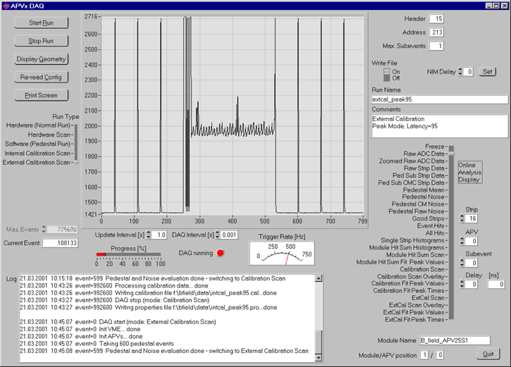
Fig. shows a screenshot of the data acquisition software. The
displayed waveform is the raw ADC output of an APV25S1 with an external calibration signal
applied to four channels.
The most important settings of the APV DAQ software are made on the GUI. Many other adjustment values are written into a configuration file, which is read by the program at startup. Thus, the system is scalable and very flexible, yet still easy to handle for the normal user.