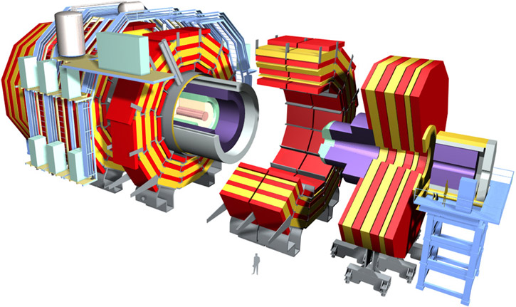
Fig. ![[*]](crossref.gif) shows the full CMS detector [5,6],
which is
shows the full CMS detector [5,6],
which is ![]() in diameter,
in diameter, ![]() long and weighs
long and weighs ![]() . It relies on four principal sub-systems:
A high-quality central tracking system (pink and yellow), surrounded by an electromagnetic
calorimeter (green), a hermetic hadron calorimeter (purple) and finally a muon detector
(red and yellow).
. It relies on four principal sub-systems:
A high-quality central tracking system (pink and yellow), surrounded by an electromagnetic
calorimeter (green), a hermetic hadron calorimeter (purple) and finally a muon detector
(red and yellow).
All subsystems of the experiment are divided into a cylindrical barrel part and the two facing endcap sections. The ``forward'' region, shown on the scaffold to the right, is further away from the interaction point at very small angles. This arrangement gives a good coverage of almost everything arising from a collision, which is important for the reconstruction of events.
A short introduction will be given to the components of the CMS experiment from the innermost to the outermost detectors. Fig.
shows a longitudinal view of CMS, where the origin denotes
the interaction point.
The angle specifications on top and
left are given in units of pseudorapidity
The central tracker consists of three pixel layers and ten strip layers.
Its task is to measure the tracks of charged particles with a minimum of interaction.
Originally, Micro-Strip Gas Chambers (MSGCs) were planned for its outer part.
However, problems were repeatedly reported concerning aging and high voltage (HV) stability.
Thus, the CMS Tracker community decided to build an all-silicon tracker [7,8]
instead, which now covers a sensitive area of ![]() .
The Tracker, as it is the main topic of
this thesis, will be discussed in detail in chapter .
.
The Tracker, as it is the main topic of
this thesis, will be discussed in detail in chapter .
The electromagnetic calorimeter (ECAL) consists of approximately 76000 scintillating ![]() crystals with a depth of
crystals with a depth of ![]() (corresponding to 25 radiation lengths
(corresponding to 25 radiation lengths ![]() )
and a cross-section of
)
and a cross-section of
![]() . Electrons and photons are converted
to light pulses, which are read out by silicon avalanche photodiodes.
A small loss in attenuation of a few percent due to color center formation
is observed from radiation. This effect can be calibrated with light injection
into the crystal.
. Electrons and photons are converted
to light pulses, which are read out by silicon avalanche photodiodes.
A small loss in attenuation of a few percent due to color center formation
is observed from radiation. This effect can be calibrated with light injection
into the crystal.
The main part of the hadron calorimeter (HCAL) is located inside the magnet, which is
surrounded by a an additional small part in the central region (``tail catcher'').
The central HCAL consists of a brass/scintillator sampling calorimeter. Its scintillation
light is captured, wavelength shifted and guided to hybrid photodiodes.
The active depth of the HCAL exceeds nine nuclear interaction lengths ![]() ,
corresponding to more than
,
corresponding to more than ![]() containment of hadronic cascades.
The forward part of the HCAL
consists of a steel absorber with quartz fibers. Traversing charged particles produce
Cherenkov light in the fibers which is guided to photomultipliers.
containment of hadronic cascades.
The forward part of the HCAL
consists of a steel absorber with quartz fibers. Traversing charged particles produce
Cherenkov light in the fibers which is guided to photomultipliers.
The calorimeters are intended for energy measurement and triggering. They are surrounded by a
superconducting coil providing a solenoidal magnetic field of ![]() . The tracks of charged
particles bend in this magnetic field
. The tracks of charged
particles bend in this magnetic field ![]() which allows to measure the polarity of their
charge
which allows to measure the polarity of their
charge ![]() and, assuming elementary charge, their momentum
and, assuming elementary charge, their momentum ![]() using the relation
using the relation
The Muon System consists of four stations in both barrel (
![]() ) and endcap
(
) and endcap
(
![]() ) parts, which are integrated in the iron return yoke of the magnet.
In the barrel part, each station consists of twelve layers of Drift Tube Chambers (DT).
Resistive Plate Chambers (RPC) are used for bunch crossing identification and provide
a cut on the muon transverse momentum at the first level trigger.
In the endcap region, each station consists of six stations of Cathode Strip Chambers (CSC).
) parts, which are integrated in the iron return yoke of the magnet.
In the barrel part, each station consists of twelve layers of Drift Tube Chambers (DT).
Resistive Plate Chambers (RPC) are used for bunch crossing identification and provide
a cut on the muon transverse momentum at the first level trigger.
In the endcap region, each station consists of six stations of Cathode Strip Chambers (CSC).
Four logic blocks make up the Trigger and Data Acquisition System. The first two stages,
front-end detector electronics and first level trigger processors,
are synchronous and pipelined. The first level trigger has to reduce the ![]() bunch crossing rate to an event rate of
bunch crossing rate to an event rate of ![]() by filtering only interesting events.
This trigger decision has a delay of
by filtering only interesting events.
This trigger decision has a delay of ![]() in relation to the corresponding
bunch crossing. To avoid dead time, the data collected within this period must be
stored in the front-end in order to pass it on after a trigger request.
in relation to the corresponding
bunch crossing. To avoid dead time, the data collected within this period must be
stored in the front-end in order to pass it on after a trigger request.
The two later stages are a large switching network (``event builder'') with a throughput
of
![]() and an on-line event filtering system implemented in a computer farm.
These stages are made of commercial components and thus can be upgraded as technology develops.
and an on-line event filtering system implemented in a computer farm.
These stages are made of commercial components and thus can be upgraded as technology develops.
The combined information of all detector subsystems is used for the total event reconstruction and quantification. While the silicon tracker is intended for momentum and polarity identification, the energy is measured by the calorimeters, and penetrating muons are detected in the outermost layer. The triggering information is derived from calorimeters and the muon system.