The behavior of APV25S1 and optical lasers (see section ![[*]](crossref.gif) , p. )
was tested in a strong magnetic field in collaboration with the Institute of Material Physics at the
Vienna University [68].
The helium-cooled, superconducting magnet provides a homogeneous flux density of up to
, p. )
was tested in a strong magnetic field in collaboration with the Institute of Material Physics at the
Vienna University [68].
The helium-cooled, superconducting magnet provides a homogeneous flux density of up to ![]() .
Our tests were performed in the regime of
.
Our tests were performed in the regime of ![]() up to
up to ![]() , where handling is much easier at
reduced helium consumption. Moreover, the magnetic field in the CMS tracker is only
, where handling is much easier at
reduced helium consumption. Moreover, the magnetic field in the CMS tracker is only ![]() .
.
An APV25S1 chip was positioned in three orthogonal orientations with respect to the magnetic field.
These positions are denoted A, B and C in fig. .
The mechanical support is designed to fit into the magnet core which is ![]() in diameter.
in diameter.
 |
Noise, internal and external calibration were measured at ![]() ,
, ![]() and
and ![]() .
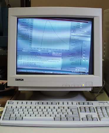
The presence of the magnetic field was easily observed on the cathode ray tube (CRT) monitor,
which was located
in the stray field about
.
The presence of the magnetic field was easily observed on the cathode ray tube (CRT) monitor,
which was located
in the stray field about ![]() away from the magnet. The distorted image of the DAQ
software is shown in fig. .
away from the magnet. The distorted image of the DAQ
software is shown in fig. .
 |
 |
shows an overlay plot of the internal calibration waveform in deconvolution mode
for the three different orientations (A, B and C) and magnetic fields between