

Next: APV25 Magnetic Field Test
Up: APVMUX Test (February 2001)
Previous: Calibration and Noise
Contents
Figure:
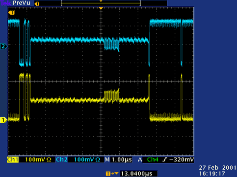
Positive (bottom) and negative (top) outputs of the APVMUX after
amplification by the repeater. A group of channels on the even APV is internally pulsed.
 |
Figure:
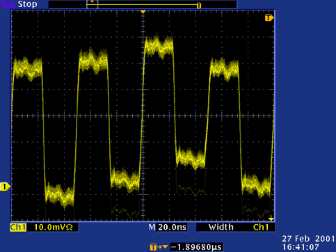
Zoomed view of the APVMUX switching between pulsed and non-pulsed
APV channels.
 |
The crucial characteristic of the APVMUX is its switching speed. If the switches were too slow,
a signal in one chip would drop its shadow in the second chip data. To test the APVMUX switching
behavior, the even APV25 was pulsed with internal calibration, while the odd chip, connected to
the same multiplexer channel, remained at pedestal level (see section ![[*]](crossref.gif) ,
p.
,
p. ![[*]](crossref.gif) , for APVMUX details).
Fig.
, for APVMUX details).
Fig. ![[*]](crossref.gif) shows the corresponding output of the APVMUX after amplification
by the repeater board.
This oscilloscope screenshot is the measured equivalent of fig.
shows the corresponding output of the APVMUX after amplification
by the repeater board.
This oscilloscope screenshot is the measured equivalent of fig. ![[*]](crossref.gif) , p.
, p. ![[*]](crossref.gif) .
Zooming into the
region of the pulsed channels, it is obvious that the switching procedure is extremely fast
and precise (fig.
.
Zooming into the
region of the pulsed channels, it is obvious that the switching procedure is extremely fast
and precise (fig. ![[*]](crossref.gif) ).
A rise time of approximately
).
A rise time of approximately  has been measured, including the amplifier on the repeater
board and the oscilloscope, which actually account for the major fraction of this value.
The crosstalk of signals on the even chip onto the odd has also been measured and
quantified with the APV readout system.
As expected from the oscilloscope screenshots, virtually no crosstalk was observed with this measurement.
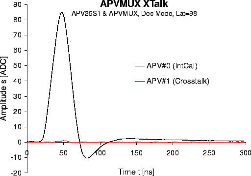
Fig. ![[*]](crossref.gif) shows the internal calibration waveforms in deconvolution mode for
both pulsed (black) and adjacent (red) channels.
shows the internal calibration waveforms in deconvolution mode for
both pulsed (black) and adjacent (red) channels.
Figure:
Averaged internal calibration waveform of the even APV25S1 chip (black)
and the negligible crosstalk in the neighboring channels of the odd chip (red).
 |
The relative crosstalk amplitudes (tab. ![[*]](crossref.gif) ) are about
) are about  and thus
negligible, since the noise level is about one order of magnitude higher.
For comparison, a crosstalk in the order of
  was obtained with the
  bandwidth ADC
version because of slower transients.
Table:
Relative crosstalk amplitudes observed in the odd APV when pulsing the even
chip.
|
Mode |
Relative crosstalk |
|
Peak |
 |
|
Deconvolution |
 |
|


Next: APV25 Magnetic Field Test
Up: APVMUX Test (February 2001)
Previous: Calibration and Noise
Contents
Markus Friedl
2001-07-14


![[*]](crossref.gif) ,
p.
,
p. ![[*]](crossref.gif) , for APVMUX details).
Fig.
, for APVMUX details).
Fig. ![[*]](crossref.gif) shows the corresponding output of the APVMUX after amplification
by the repeater board.
This oscilloscope screenshot is the measured equivalent of fig.
shows the corresponding output of the APVMUX after amplification
by the repeater board.
This oscilloscope screenshot is the measured equivalent of fig. ![[*]](crossref.gif) , p.
, p. ![[*]](crossref.gif) .
Zooming into the
region of the pulsed channels, it is obvious that the switching procedure is extremely fast
and precise (fig.
.
Zooming into the
region of the pulsed channels, it is obvious that the switching procedure is extremely fast
and precise (fig. ![[*]](crossref.gif) ).
A rise time of approximately
).
A rise time of approximately ![[*]](crossref.gif) shows the internal calibration waveforms in deconvolution mode for
both pulsed (black) and adjacent (red) channels.
shows the internal calibration waveforms in deconvolution mode for
both pulsed (black) and adjacent (red) channels.

![[*]](crossref.gif) ) are about
) are about ![]() and thus
negligible, since the noise level is about one order of magnitude higher.
For comparison, a crosstalk in the order of
and thus
negligible, since the noise level is about one order of magnitude higher.
For comparison, a crosstalk in the order of ![]() was obtained with the
was obtained with the ![]() bandwidth ADC
version because of slower transients.
bandwidth ADC
version because of slower transients.