

Next: Source Test
Up: APV25 Laboratory Tests (2000/2001)
Previous: APV25 Laboratory Tests (2000/2001)
Contents
Calibration and Noise
Precise calibration measurements were performed on the APV25S1, which was mounted on a single-chip
hybrid (fig. ![[*]](crossref.gif) , p.
, p. ![[*]](crossref.gif) ). Small capacitors are integrated
in the PCB (printed circuit board) hybrid to allow pulsing by an applied voltage step.
The placement of such capacitors with an associated voltage divider is
difficult in terms of precision and excess noise introduced to the corresponding channels.
). Small capacitors are integrated
in the PCB (printed circuit board) hybrid to allow pulsing by an applied voltage step.
The placement of such capacitors with an associated voltage divider is
difficult in terms of precision and excess noise introduced to the corresponding channels.
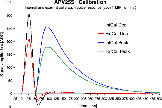
Pulse scans were performed for both internal and external calibration. The results
with a nominal charge injection of  (
( )
are shown in fig.
 ![[*]](crossref.gif) for both peak and deconvolution modes.
The waveform with external pulsing is not perfectly straight due to limited precision of the
external delay used for this scan. While the shapes for internal and external calibration
are congruent, their amplitudes differ considerably. The precision of the internal calibration
circuit is limited for reasons discussed in section
for both peak and deconvolution modes.
The waveform with external pulsing is not perfectly straight due to limited precision of the
external delay used for this scan. While the shapes for internal and external calibration
are congruent, their amplitudes differ considerably. The precision of the internal calibration
circuit is limited for reasons discussed in section ![[*]](crossref.gif) , p.
, p. ![[*]](crossref.gif) . For this particular sample,
the internal calibration charge is about
. For this particular sample,
the internal calibration charge is about  higher than the externally applied charge
with an estimated accuracy of
  .
.
Figure:
Comparison of the APV25S1 response to internal and external
calibration pulsing for both peak and deconvolution modes.
 |
With a known calibration amplitude, the APV noise can be obtained in absolute numbers. We will use
the external calibration for this evaluation, since it is the worse case in terms of absolute noise.
Thus, the resulting numbers rather give an upper limit for the noise figure.
After subtracting the noise of the readout system, the resulting equivalent noise charge (ENC)
for channels with no capacitive load is shown in tab. ![[*]](crossref.gif) .
These numbers perfectly agree with the design values
and with manufacturer's tests [64].
.
These numbers perfectly agree with the design values
and with manufacturer's tests [64].
Table:
Comparison of the APV25S1 equivalent noise charge design values to measurements with
external calibration. The noise of the readout system has been subtracted.
|
Mode |
Design |
Measurement |
|
|
![$\rm ENC\,[e]$](img279.gif) |
![$\rm ENC\,[e]$](img279.gif) |
|
Peak |
250 |
267 |
|
Deconvolution |
400 |
425 |
|


Next: Source Test
Up: APV25 Laboratory Tests (2000/2001)
Previous: APV25 Laboratory Tests (2000/2001)
Contents
Markus Friedl
2001-07-14
![[*]](crossref.gif) , p.
, p. ![[*]](crossref.gif) ). Small capacitors are integrated
in the PCB (printed circuit board) hybrid to allow pulsing by an applied voltage step.
The placement of such capacitors with an associated voltage divider is
difficult in terms of precision and excess noise introduced to the corresponding channels.
). Small capacitors are integrated
in the PCB (printed circuit board) hybrid to allow pulsing by an applied voltage step.
The placement of such capacitors with an associated voltage divider is
difficult in terms of precision and excess noise introduced to the corresponding channels.
