Unlike most other particle beams, PSI provides a continuous beam with an LHC-like bunch
structure of ![]() . Since LHC and the APVs are only clocked with
. Since LHC and the APVs are only clocked with ![]() , a dedicated
PLL-based NIM module has been developed, which derives a synchronous
, a dedicated
PLL-based NIM module has been developed, which derives a synchronous
![]() signal from the PSI clock. Moreover, this module produces a short
SYNC pulse when both clocks are in phase, which occurs every
signal from the PSI clock. Moreover, this module produces a short
SYNC pulse when both clocks are in phase, which occurs every ![]() (fig.
(fig. ![[*]](crossref.gif) ).
The SYNC pulse is used to select particle triggers which are in phase with the APV clock.
By this synchronization, four out of five possible triggers are discarded, but it is
ensured that passing triggers are in phase with the APV clock. Thus, the system environment
is very close to what it will be in CMS.
).
The SYNC pulse is used to select particle triggers which are in phase with the APV clock.
By this synchronization, four out of five possible triggers are discarded, but it is
ensured that passing triggers are in phase with the APV clock. Thus, the system environment
is very close to what it will be in CMS.
 |
Normally, the beam was set to low intensity at the order of
![]() with a particle trigger derived from a scintillator with an area of
with a particle trigger derived from a scintillator with an area of
![]() ,
watched by two photomultiplier tubes. The photomultipliers were equipped with preamplifiers
and operated at relatively low voltage to avoid saturation at high beam intensity.
Several dedicated runs were taken at a particle rate of up to
,
watched by two photomultiplier tubes. The photomultipliers were equipped with preamplifiers
and operated at relatively low voltage to avoid saturation at high beam intensity.
Several dedicated runs were taken at a particle rate of up to
![]() .
At this intensity, it is not necessary to use the scintillator, because every bunch
is filled with 2.5 particles in average. Thus, the SYNC pulse alone is good for triggering
at high intensity. In that case, the measured beam profile is no longer restricted to the
area covered by the scintillator, but reflects the actual beam spread.
.
At this intensity, it is not necessary to use the scintillator, because every bunch
is filled with 2.5 particles in average. Thus, the SYNC pulse alone is good for triggering
at high intensity. In that case, the measured beam profile is no longer restricted to the
area covered by the scintillator, but reflects the actual beam spread.
Several silicon detector modules were tested at PSI, two of which were
constructed at HEPHY. A module consisting of two 4" sensors with 1024 strips, read out by eight
APV6 chips, was built within the framework of a module production milestone. Therefore, this
module
was called ``Vienna Milestone'' (VM). The ``Vienna APV25'' (V25; fig. , p. )
module with two 6" sensors and
APV25S0 readout was already presented in section , p. .
Several other institutes within the CMS collaboration joined these tests and provided their detector
modules. In the May test, a total of five APV6 and two APV25S0 modules were tested, while in
December, all six modules were read out with the new APV25S1 chip.
Tab. gives an overview of the properties for the modules tested at PSI.
The module order corresponds to the arrangement in the beam
as seen by the particles (from top to bottom).
Some of the silicon detectors were previously irradiated with CMS-like doses
to study their performance in comparison with virgin sensors.
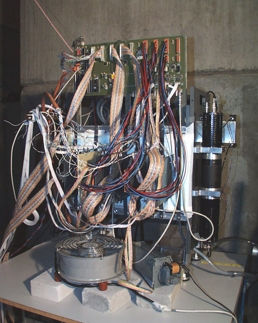
This required an ambient temperature of
![]() , which was
provided by the cooling box, shown in fig. .
, which was
provided by the cooling box, shown in fig. .
 |
The main results of the PSI module tests are presented in the following sections, while additional information is available at [12].